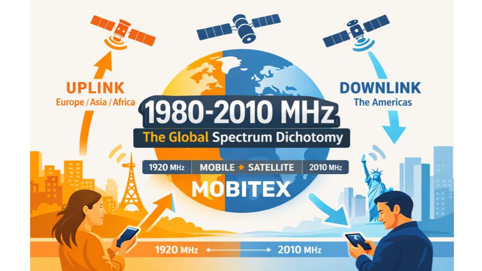
The 1980-2010 MHz frequency range represents one of the most fascinating examples of how the same radio spectrum can serve completely opposite purposes depending on where you are in the world. While a smartphone in London uses these frequencies to transmit voice and data to a cell tower, an identical device in New York might be receiving data from a tower on the exact same frequency. This curious dichotomy has shaped global mobile device design and cellular network architecture for over two decades.
The Great Frequency Divide
Europe, Asia, and Africa: Band 1 Uplink
In most of the world—including Europe, Asia, Africa, and parts of the Americas—the 1980-2010 MHz range serves as part of the Band 1 uplink spectrum. This is the portion of spectrum where mobile devices transmit to base stations. More specifically, it’s the upper segment of the larger 1920-2025 MHz uplink allocation that pairs with a downlink band at 2110-2170 MHz.
When you make a phone call in Paris or send a photo from Tokyo, your smartphone is likely using frequencies in this range to transmit that information to the nearest cell tower. The technology has evolved from 3G UMTS through 4G LTE Band 1 to modern 5G NR n1 networks, but the fundamental allocation remains the same: mobile devices talk up, base stations listen.
Key characteristics for Europe/Asia:
- Direction: Uplink (UE → Base Station)
- 3GPP Designation: Band 1 (LTE/UMTS), n1 (5G NR)
- Paired with: 2110-2170 MHz downlink
- Duplex gap: 95 MHz separation
- Typical power: +21 to +24 dBm from mobile devices
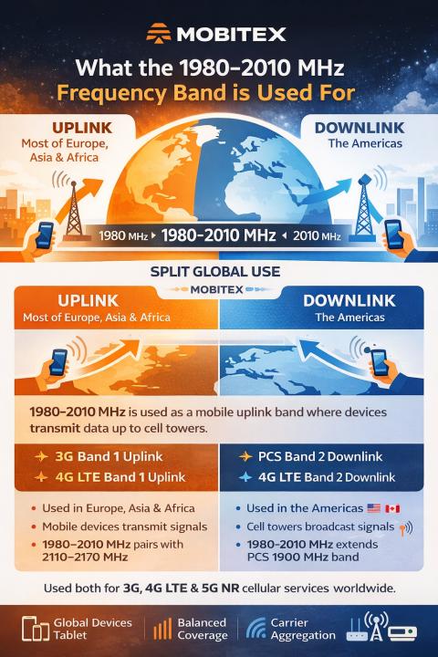
Americas: Band 2 Downlink Extension
The Americas tell a different story. In the United States, Canada, and parts of Latin America, the lower portion of this range (1981-1990 MHz) serves as a continuation of the Band 2 downlink allocation. Here, base stations transmit to mobile devices—the exact opposite direction.
This creates the remarkable situation where a frequency like 1985 MHz carries a mobile device’s voice uplink in Berlin but a cell tower’s data downlink in Boston. The same electromagnetic frequency, traveling at the speed of light, but flowing in opposite directions depending on the continent.
Key characteristics for Americas:
- Direction: Downlink (Base Station → UE) for 1981-1990 MHz
- 3GPP Designation: Band 2 extension
- Paired with: 1850-1910 MHz uplink
- Duplex gap: 80 MHz separation
- Typical power: 43-49 dBm from base stations
Technical Specifications
Propagation Characteristics
At approximately 2 GHz, these frequencies offer excellent propagation characteristics for cellular networks. The free space path loss at 1 kilometer is around 98 dB, increasing to 118 dB at 10 kilometers. This represents a sweet spot: better building penetration than higher frequency bands (2.6 GHz, 3.5 GHz) but more spectrum-efficient than low-band alternatives (700-900 MHz).
Coverage ranges vary by environment:
- Urban areas: 0.5-2 km cell radius
- Suburban zones: 2-10 km
- Rural deployments: 5-15 km, extending to 35 km with macro towers
Building penetration is moderate at this frequency, with typical losses of 10-20 dB through modern construction. This makes indoor coverage achievable with outdoor macro cells in many cases, though dense urban environments often require small cells or distributed antenna systems for reliable indoor service.
Power and Performance
The power levels differ dramatically between the two regional allocations due to their opposite transmission directions.
Europe/Asia (Mobile Device Transmit):
- Maximum transmit power: +24 dBm (250 milliwatts)
- Typical urban operation: +21 dBm
- Dynamic power control: Adjusts from +24 dBm down to -50 dBm based on link conditions
- Battery-powered operation: Critical for smartphone battery life
Americas (Base Station Transmit, where Band 2 extends):
- Conducted power: 43-49 dBm (20-80 watts)
- With antenna gain: Up to 61 dBm EIRP
- Grid-powered with battery backup
- Continuous transmission capability
This power differential reflects the asymmetric nature of cellular networks. Base stations with their grid power and high-gain antennas can transmit at much higher power levels than battery-constrained mobile devices. The Band 1 uplink allocation requires mobile devices to overcome this power imbalance through sophisticated receiver technology at the base station, achieving sensitivities of -120 to -130 dBm.
Modern Technologies
Both allocations support the full evolution of mobile technology:
3G Era (2000s):
- UMTS with WCDMA modulation
- 5 MHz channel bandwidth
- Circuit-switched voice, packet data up to 42 Mbps (HSPA+)
4G LTE (2010s):
- OFDMA downlink (Americas), SC-FDMA uplink (Europe/Asia)
- Flexible bandwidths: 5, 10, 15, 20 MHz
- MIMO configurations: 2×2, 4×4
- Modulation: QPSK through 256-QAM
- Peak speeds: 150-300+ Mbps
5G NR (2020s):
- Flexible numerology and bandwidth
- Massive MIMO: Up to 64×64 antenna arrays
- Sub-10ms latency, <1ms for URLLC
- Network slicing, beamforming
- Multi-gigabit speeds when aggregated with other bands
Network Architecture
Spectrum Pairing
The FDD (Frequency Division Duplex) architecture requires carefully paired spectrum:
Europe/Asia Band 1:
- Uplink: 1920-2025 MHz (includes our 1980-2010 range)
- Downlink: 2110-2170 MHz
- Duplex gap: 95 MHz
- Allows simultaneous bidirectional communication
Americas Band 2:
- Uplink: 1850-1910 MHz
- Downlink: 1930-1990 MHz (our range is the upper portion)
- Duplex gap: 80 MHz
- PCS 1900 allocation from 1990s
Carrier Aggregation
Modern networks don’t use these frequencies in isolation. Carrier aggregation combines multiple bands for higher throughput:
Common Band 1 combinations:
- Band 1 + Band 3 (1800 MHz)
- Band 1 + Band 7 (2600 MHz)
- Band 1 + Band 8 (900 MHz)
Common Band 2 combinations:
- Band 2 + Band 4 (AWS)
- Band 2 + Band 12 (700 MHz)
- Band 2 + Band 66 (extended AWS)
Global Deployment
Operators and Coverage
Europe/Asia Band 1 deployment is nearly universal:
- Vodafone, Orange, Telefónica across Europe
- China Mobile, China Unicom in Asia
- NTT DoCoMo in Japan
- Deployed in 170+ countries worldwide
- Primary IMT band for most of the world
Americas Band 2 presence varies:
- AT&T, Verizon, T-Mobile in the United States
- Rogers, Telus, Bell in Canada
- Telcel in Mexico
- Extension to 1990 MHz market-dependent
Device Ecosystem
The opposite directional allocations haven’t prevented a unified device ecosystem. Modern smartphones include universal Band 1 and Band 2 support:
Consumer devices:
- Apple iPhone (all recent LTE/5G models)
- Samsung Galaxy series
- Google Pixel devices
- Cellular-enabled tablets and laptops
Chipset manufacturers have solved the complexity:
- Qualcomm Snapdragon: Universal band support
- MediaTek Dimensity: Multi-band 5G
- Samsung Exynos: Integrated modems
- Apple A-series: Custom 5G integration
This means a single smartphone purchased in London will work seamlessly on Band 1 networks across Europe and Asia, then switch to Band 2 (among others) when roaming in the United States. The device’s software and RF front-end automatically configure for the local allocation.
Interference Management
The Challenge of Opposite Directions
The opposite directional use creates minimal cross-border interference issues since transmit and receive are separated. However, each allocation faces its own challenges:
Europe/Asia Uplink Issues:
- Mobile device power control critical for capacity
- Uplink interference limits cell edge performance
- Requires advanced receiver technology (interference cancellation)
- Cross-border coordination needed in Europe
Americas Downlink Concerns:
- Base station emission masks protect adjacent channels
- Coordination between operators at band edges
- DAS (Distributed Antenna System) requires careful isolation
- Cross-border issues at US-Canada and US-Mexico borders
Co-channel Management
Within each region, operators must manage interference:
Uplink (Europe/Asia):
- Fractional frequency reuse
- Uplink power control algorithms
- Interference rejection combining
- Coordinated scheduling
Downlink (Americas):
- Inter-cell interference coordination
- Beamforming and beam steering
- Enhanced ICIC (Inter-Cell Interference Coordination)
- FeICIC for heterogeneous networks
Regulatory Framework
ITU Allocations
The International Telecommunication Union’s Radio Regulations define the global framework:
ITU Regions 1 and 3 (Europe/Africa/Asia):
- Primary allocation: MOBILE
- IMT uplink designation
- Part of 1980-2025 MHz uplink band
ITU Region 2 (Americas):
- Mixed allocation
- Some countries: IMT (Band 1 uplink)
- USA/Canada: PCS (Band 2 downlink extension)
- Regional variations complicate coordination
National Regulators
Europe:
- CEPT (European Conference of Postal and Telecommunications Administrations)
- Harmonized Band 1 allocation across EU
- Ofcom (UK), ARCEP (France), BNetzA (Germany)
Asia:
- National regulators in each country
- Generally aligned with ITU Region 3
- Massive Band 1 deployments in China, India, Japan
Americas:
- FCC (United States): Part 27 for PCS
- ISED (Canada): SRSP-512
- Country-specific in Latin America
The Future: 5G and Beyond
5G NR Evolution
The 1980-2010 MHz range continues its role in 5G networks:
Europe/Asia 5G NR n1:
- Anchor band for 5G deployment
- Combines with mid-band (3.5 GHz) and mmWave
- Network slicing enables diverse services
- Enhanced mobile broadband, IoT, URLLC
Americas 5G NR n2:
- Coverage layer for 5G
- Complements C-band (3.7-3.98 GHz) capacity
- Carrier aggregation across multiple bands
Spectrum Efficiency Gains
Modern 5G technology extracts more capacity from the same frequencies:
Advanced techniques:
- Massive MIMO: 64+ antenna elements
- Beamforming: Focused energy to specific users
- Dynamic TDD: Flexible uplink/downlink allocation (in TDD bands)
- Network intelligence: AI-driven optimization
Long-term Outlook
This spectrum will remain valuable for decades:
Advantages:
- Excellent propagation characteristics
- Mature ecosystem (billions of devices)
- Established global allocation
- Technology-neutral licensing enables evolution
Challenges:
- Spectrum congestion in dense urban areas
- Regional fragmentation (uplink vs. downlink)
- Refarming from legacy 3G systems
- Competition from new mid-band allocations
Practical Implications
For Network Operators
The 1980-2010 MHz range represents:
- Coverage foundation: Excellent propagation for wide-area networks
- Capacity supplement: When combined with higher-frequency bands
- Roaming complexity: Managing opposite directional allocations globally
- Investment longevity: Spectrum valuable across multiple technology generations
For Device Manufacturers
Design considerations include:
- Multi-band support: Must handle both Band 1 and Band 2
- Duplex filters: Different requirements for uplink vs. downlink
- Power amplifiers: Optimized for regional allocation
- Global SKUs: Single hardware design for worldwide markets
For Consumers
What this means for users:
- Seamless roaming: Modern phones work globally
- Network performance: Part of operator’s coverage strategy
- 5G services: Enables nationwide 5G coverage
- Future-proof: Devices support current and future technologies
Conclusion
The 1980-2010 MHz frequency range exemplifies both the complexity and elegance of modern wireless communications. What appears as a simple 30 MHz slice of radio spectrum actually represents two fundamentally different network architectures separated by geography: Europe and Asia’s uplink transmissions versus America’s downlink signals.
This dichotomy has driven innovation in device design, forcing manufacturers to create radios capable of operating in both modes. It has challenged network operators to deploy globally consistent services despite regional spectrum fragmentation. And it has demonstrated that even as the world moves toward 5G and eventually 6G, mid-band spectrum around 2 GHz remains critically important.
For RF engineers and spectrum professionals, this band serves as a reminder that spectrum allocation is as much about political and historical decisions as technical optimization. The fact that the same frequency carries opposite traffic directions in different parts of the world isn’t a technical limitation—it’s a testament to the flexibility of modern wireless technology and the ability of the industry to work within diverse regulatory frameworks.
As we look toward future wireless generations, the 1980-2010 MHz range will continue serving billions of users worldwide, whether they’re transmitting their voice upward to a cell tower in Shanghai or receiving a video stream downward from a base station in San Francisco.
Key Takeaways
- 1980-2010 MHz serves opposite purposes: Europe/Asia uplink vs. Americas downlink
- Part of primary cellular bands: Band 1 (global) and Band 2 (Americas)
- Excellent propagation: 2 GHz offers optimal balance of coverage and capacity
- Mature ecosystem: Billions of devices support these frequencies
- 5G evolution: Continues as anchor band for next-generation networks
- Regional complexity: Global devices must support both allocations